ProBuilder Plus User Guide
Intro
ProBuilder Plus is a complete overhaul of Unity’s ProBuilder, built by the original author, with Overdrive community help 💖🙇
- Dozens of new/improved, long-requested features
- Choose old-school or modernized UI, with significant improvements to both
- Non-destructive live previews for all actions
- Direct editing of colors, UVs, materials, positions, etc
- Seamless integration with Overdrive Toolset accelerators
New in PB+
The below is a brief overview of the new abilities and improvements in PB+, vs standard ProBuilder. More on the way, and I’m always open to feature requests!
- New Actions Overlay UI
- Standard overlay with all actions
- Customizable to also show edit modes and window buttons if desired
- Minimal toolbar versions included
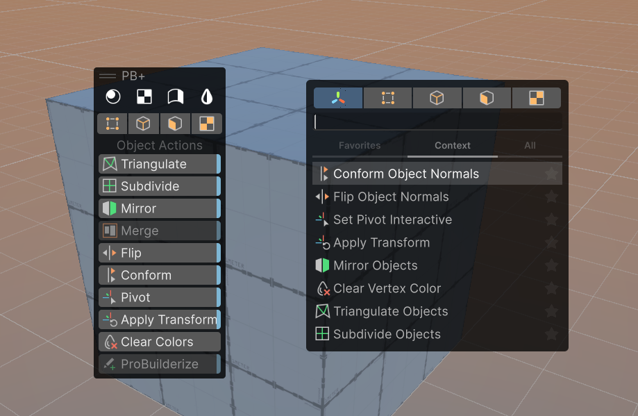
- New Action Pal integration
- View, search, and Favorite actions
- Use as an always-on overlay, or at-mouse popup
- New edit mode – “UV / Texture”
- New in-scene handles for move, rotate, scale textures
- New ability to snap to vertex when moving textures on faces (this one is amazingly useful!)
- New “UV Box” visual, really helps understand how the texture is placed on the surface(s)
- New +/- buttons for quick setting of texture position, rotation, scale
- New in-scene actions for UVs, one click Planar, Box, Fit, Reset, Stretch, Flip
- New Texture Face Group visual and UI, much more intuitive
- New Direct Edit Overlay
- Directly view and set colors, materials, smoothing groups, UV settings, and more
- Directly view and set position, per-axis (eg, move a mixed group of vertices to exactly 3.5 on Y axis, without affecting other axis)
- New for ALL actions: settings with live preview visuals showing exactly what will be created, removed, modified, etc – no more guessing!
- New Object Actions
- Merge: new ability to choose pivot object
- New Set Pivot Interactive: Pick exact position for the pivot
- New Apply Transform: Reset position, rotation, scale separately
- New shared element actions
- Offset: move elements an exact distance, using specific directions or even a chosen surface direction
- Clear Vertex Colors: clears all colors from elements, quickly reverting back to basic
- Dissolve: remove edges and vertices without losing faces
- New for Vertex Mode
- Delete: crazy that we never had this. Now you do 🙂
- Weld: new option, Weld to Center or Specific
- Collapse: new option, Weld to Center or Specific
- New for Edge Mode
- Delete: again, how did we never have this? enjoy!
- Connect: new ability to offset the connections
- Bridge: new ability to bridge entire borders
- Add Loop: new ability to offset the loop
- New for Face Mode
- New Inset action: smart, offset-based inset of faces
- New for Selection
- Grow Selection: many more options such as matching color and face
- New Action: Select Face Path. No more guessing ring/loop on faces, just select two and it follows!
- New Action: Select By Color
- New Action: Select By Material
- New Action: Select by Angle
- New Action: Select Similar (a complex, multi-filter version of the quick actions above)
Quick Start
1) Select or create a ProBuilder object
- Use the Unity-standard creation tools, or Action Pal
- More Info – Creation
2) Choose Your Own (UI) Adventure
- Old School UI: Enable the “PB+” overlay, and place it in the view as you like
- Action Pal: Press “A” to open Action Pal at your mouse (or, enable and place the Action Pal overlay)
- More Info – PB+ Overlay
- More Info – Action Pal
3) Select and Edit Elements
- From your chosen UI, choose Vertex, Edge, Face, or UV
- Now you can select and interact with those elements, and the Actions will update to match
- Choose “GameObject” to return to standard mode

4) Use an Action
- Select the elements or objects to edit
- View the UI – hover for info, click to activate
- Adjust settings in the preview overlay, click Confirm to apply, or Cancel/ESC to abort
- More Info – Actions
5) Direct Edit
- Enable the “PBi” overlay, place it in the view as you like (it will only show with PB items selected)
- Select the elements to edit
- In the PB Info Overlay, view and modify the elements directly (color, material, UV position, etc)
- More Info – ProBuilder Info Overlay
Creating Editable shapes
PB+ doesn’t add new creation methods – should it? I’m open to feature requests!
Quick-create a ProBuilder shape:
- From the top menu, choose “GameObject > ProBuilder > (cube, sphere, etc)
- The shape will appear at your “focused” point in the Scene View
Draw a ProBuilder shape:
- In the standard Tools Overlay, click-hold the “Create ProBuilder Shape” tool
- Pick the shape you wish to create
- On any surface or grid, draw out the shape points
- Click the first point, drag to the second point, release, click the third point
- The shape is created as drawn
With the Draw tool, you can also hold SHIFT to see a pre-viz of the shape, as you hover over surfaces, then simply click once to place it right there. Neat!Any type of ProBuilder shape can always be swapped to another shape type (eg, Cube to Stairs, etc), and all the properties are non-destructively editable until you change the mesh directly. A great option for quick and early prototyping!Using the PB+ Overlay UI
PB+ gives you all the options! Use the “old school” style overlay with buttons, or the quick-and-contextual Action Pal integration (requires Action Pal)
Enabling the PB+ Overlay
Unity provides several methods to open overlays:
- Right-click on the Scene View header tab, and choose “Show Overlay Menu”, then enable PB+ (this is slow, please use any other way 😅)
- In the Scene View, press the “Show Overlay Menu” keyboard shortcut (see Shortcut Manager to set this), then enable PB+
- In the Overlay Menu Toolbar, click the “PB+” overlay toggle to enable it

Overlay, ah, Overview
The overlay has 3 sections:
- Editor Window Buttons (white) – these open the funky old Material Editor, UV Editor, Smoothing Groups, and Vertex Coloring panels. I suggest to hide these (see below), and just use the new Direct Editing solution
- Edit Mode – click a mode (eg, Vertex) to enable selection and editing of this element type. Technically not needed since Unity provides these buttons in the standard Tool Settings overlay, but I know some people really prefer this! Also, Action Pal provides a more streamlined and tool-agnostic method.
- Actions – buttons for Extrude/Bridge/Subdivide etc, the mesh operations you can use with PB+. See the Action Reference for full details on those.


Right-click anywhere in the overlay to choose options, such as hiding button groups.Right-click the overlay header to choose Panel (full text) or Toolbar (horizontal or vertical) display modes. Or, simply drag into a toolbar zone (edge of the Scene View).Buttons with a blue highlight are Preview ActionsIf a button is disabled, hover to see why - usually, you need to select a certain element or type.Using PB+ With Action Pal UI
We think this is best, but we’re probably biased – you decide! Action Pal lets you instantly see, search, and favorite any available actions – including shortcut actions! It works with all of Unity (and custom tools!), no limits. See the Action Pal page for more info.
Action Pal as Overlay
- Enable the Action Pal overlay
- Place it as you like in the Scene View
- It will track your selection, tool, and edit mode, showing matching actions in the “Context” tab

Action Pal as Pop-Up
- Hover anywhere in the Scene View
- Press “A” (customizable shortcut)
- The Action Pal appears, with actions matching your current selection

Hey tool developers/tech artists! Both Action pal and the pop-up are part of the friendly Overdrive framework, for anyone to use! They're a great way to make your toolset super fast and friendly. Check out the Overdrive Framework for Devs and Other People Who Occasionally Build Custom Unity Things for more details.Using PB+ Actions
Nearly all PB+ actions are Preview Enabled, meaning you can:
- Click the button, no danger!
- The action Preview will appear, showing you a helpful indicator of what it will do
- The action Preview Overlay will also appear, with info and options
- Press “Apply” when ready (or ENTER), or cancel if not (or ESC)
This lets you easily try out actions and their options, no need to memorize or trial-and-error.

Preview Actions have a highlight on their button. Holding CTRL will hide this, and instantly apply the action on click, using the default settings.When you change the Action Preview settings, this is recorded to the ProBuilder Plus preferences, which you can edit separately as well.Direct Edit with the Info Overlay
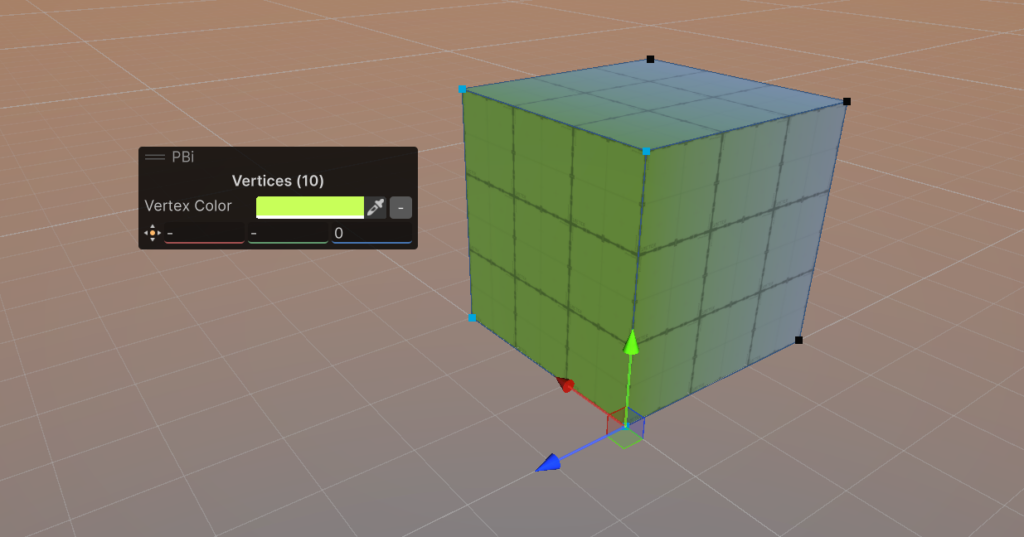
This is basically the Unity Inspector – for elements! It provides quick and functional access to the most important aspects of a vert, edge, face, or UV, without opening extra windows. Also, some of PB+ best new features!
Vertex Mode
- Vertex Color: view and set the colors for selected vertices. This will create a “fade” effect, great for grunge/dirt/occlusion.
- Position: View and set position, per axis. Fantastically useful for ensuring verts are lined up, perfectly snapped, or just in the right place.
Edge Mode
- Vertex Color: view and set the colors for the selected edges. This applies to verts, so will also “fade”.

Face Mode
- Vertex Color: view and set the vertex color of the selected faces. Unlike Edge and Vertex, this will apply with a hard edge, great for quickly indicating zones/areas/etc for level design!
- Material: view and set the material on the selected faces.
- Smooth Group: view and set the smoothing group, which enables “faking” high-poly look on simpler geometry.

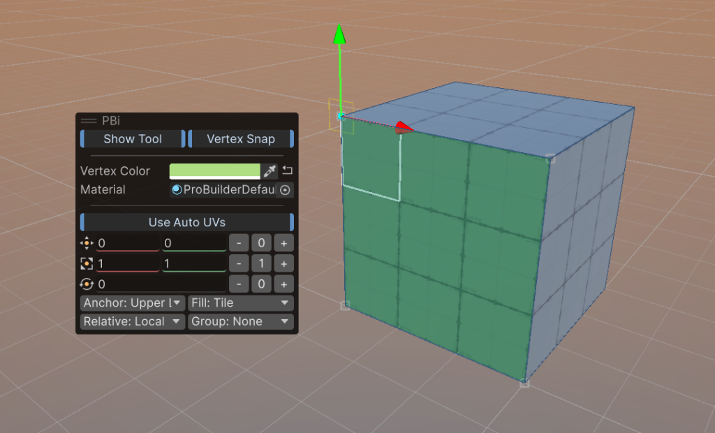
UV / Texturing Mode
We HIGHLY recommend trying this one out early! Test the basics and you'll quickly understand how simple and powerful it can be for quick texture mapping in your worlds!- Show Tool: show/hide the in-scene tool for manipulating the texture placement/rotation/scale.
- Vertex Snap: enable/disable snapping to vertices when using the tool (or, hold SHIFT)
- Vertex Color: view and set face vertex color
- Material: view and set face material
- Use Auto UVs: when ON, ProBuilder will automatically handle UVs, giving you simple options to control them (vs Manual, which is more like Blender/Max/etc)
- Texture Offset: where the texture sits on the surface
- Texture Scale: how large the texture is
- Texture Rotation: how the texture is rotated
- Anchor: Represented by the blue dot, this is where the texture considers it’s “origin” point
- Fill: Whether to fill the entire surface with the texture (without stretch), or tile (repeat), or fill with stretch.
- Group: Surfaces with the same “Group” value will be treated as one large, continuous surface.

action reference
PB+ replaces all standard actions, and adds many new ones. Details below, and feel free to request features!
Object Mode
ProBuilderize
What it Does: Converts meshes to ProBuilder objects, allowing PB to edit them
How to Use: Select non-PB mesh objects, click “ProBuilderize”. Adjust import settings, confirm.
Preview: Bounding boxes show conversion.
Settings:
- Import Quads: Preserve quads
- Import Smoothing: Apply smoothing
- Smoothing Angle: Threshold
Merge Objects
What it Does: Combines objects into one.
How to Use: Select objects, click “Merge”. Choose pivot, confirm.
Preview: Wireframe shows object affected, with cyan wireframe on the Pivot Object.
Settings:
- Pivot: Which object to use for pivot position, rotation, and scale. SHIFT-click to select in scene, or use this dropdown.

Mirror Objects
What it Does: Mirrors geometry across axes.
How to Use: Select objects, click “Mirror”. Choose axes/duplicate, confirm.
Preview: Wireframe shows mirrored geometry. Green for adding new (duplicate is on), red on the original if not duplicating (original will be removed).
Settings:
- Axes: X/Y/Z
- Duplicate: Create copy

Apply Transform
What it Does: Bakes position, rotation, scale.
How to Use: Select objects, click “Apply Transform”. Confirm.
Preview: Axis tripod showing new position and rotation of the pivot, box displaying scale.
Settings:
- Apply Position: moves the pivot to world origin
- Apply Rotation: resets the pivot rotation to world (zero)
- Apply Scale: resets the pivot scale to 1 on all axis (will not affect the object visibly)

Subdivide Objects
What it Does: Subdivides all faces on the object.
How to Use: Select objects, click “Subdivide”.
Preview: Wireframe shows new topology.
Settings: None

Triangulate Objects
What it Does: Converts all faces to triangles.
How to Use: Select objects, click “Triangulate”. Confirm.
Preview: Wireframe shows triangle layout.
Settings: None

Flip Object Normals
What it Does: Reverses all normals.
How to Use: Select objects, click “Flip”. Confirm.
Preview: Arrows show new face directions.
Settings: None

Conform Object Normals
What it Does: Aligns all normals consistently.
How to Use: Select objects, click “Conform”. Confirm.
Preview: Shading updates; preview may show arrows.
Settings: None

Set Pivot (Interactive)
What it Does: Sets object pivot position.
How to Use: Select object, click “Pivot”. Move pivot interactively, confirm.
Preview: Grey squares show vertices to be picked, purple square shows object center. On click, axis tripod shows new pivot location.
Settings: None

Clear Vertex Color
What it Does: Removes vertex color data.
How to Use: Select objects, click “Clear”.
Preview: None
Settings: None
Multi-Element Actions
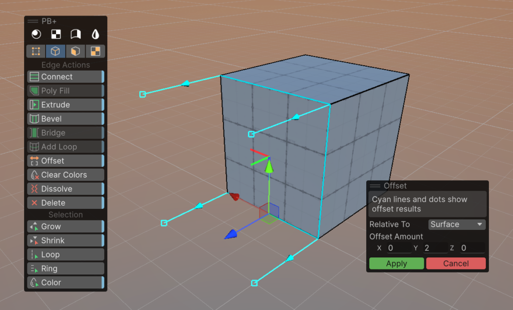
Offset Elements (Vertex, Edge, Face)
What it Does: Moves elements an exact amount, in a chosen direction.
How to Use: Select vertices/edges/faces, click “Offset”. Adjust amount and direction, confirm.
Preview: Cyan lines show movement.
Settings:
- Relative To: Average, Object, World, Surface (click surface to pick, axis tripod indicates direction)
- Amount: Offset distance

Bevel Elements (Edge, Face)
What it Does: Creates a beveled edge or face.
How to Use: Select edges/faces, click “Bevel”. Adjust amount, confirm.
Preview: Wireframe shows bevel geometry.
Settings:
- Amount: Bevel width

Poly Fill
What it Does: Fills border, or specific elements, with new faces.
How to Use: Select open edges/vertices, click “Poly Fill”. Choose Entire or exact. Confirm.
Preview: Wireframe shows edges to poly fill.
Settings:
- Use Entire Border: if enabled, the entire border will be filled. Otherwise, the selected vertices/edges are used to form the border.

Dissolve Elements (Vertex, Edge)
What it Does: Removes selected elements, merging geometry.
How to Use: Select vertices/edges, click “Dissolve”. Confirm.
Preview: Elements and their dependents are highlighted for dissolving.
Settings: None


Delete Elements (Vertex, Edge, Face)
What it Does: Deletes selected elements.
How to Use: Select vertices/edges/faces, click “Delete”. Confirm.
Preview: Elements and their dependents are highlighted in red.
Settings: None


Vertex Actions
Weld Vertices
What it Does: Merges vertices within a distance.
How to Use: Select vertices, click “Weld”. Adjust distance/center, confirm.
Preview: Lines/points show merge result.
Settings:
- Distance: Weld threshold
- Weld to Center: Use the center of each group. Otherwise, it will try to pick direction based on the active element (last-chosen vertex, SHIFT click to set)

Collapse Vertices
What it Does: Collapses selected vertices to one point.
How to Use: Select vertices, click “Collapse”, choose center on/off. Confirm.
Preview: Highlighted point shows collapse.
Settings:
- Collapse to Center: If enabled, uses a central position. Otherwise, uses the active element (last chosen vertex, SHIFT click to set)

Connect Vertices
What it Does: Connects selected vertices with edges.
How to Use: Select vertices, click “Connect”. Confirm.
Preview: Wireframe overlay shows connections.
Settings: None

Edge Actions
Extrude Edges
What it Does: Creates new geometry by extending edges.
How to Use: Select edges, click “Extrude”. Adjust distance/method, confirm.
Preview: Green lines show new edges.
Settings:
- Distance: Amount to extrude
- Method: Individual/Group

Insert Edge Loop
What it Does: Adds an edge loop to geometry.
How to Use: Select edge ring, click “Add Loop”. Adjust position, confirm.
Preview: Green lines show new edges to create.
Settings:
- Offset: amount to offset the loop
- Direction: direction of the offset
- Method: Percent or absolute units (meters)

Bridge Edges
What it Does: Connects two edges with new faces.
How to Use: Select two open edges, click “Bridge”. Choose border method. Confirm.
Preview: Wireframe overlay shows bridge(s)
Settings:
- Use Full Borders: If enabled, Bridge will attempt to connect all edges on the borders. Otherwise, just the selected edges will be bridged.

Connect Edges
What it Does: Connects selected edges with new edges.
How to Use: Select edges, click “Connect”. Confirm.
Preview: Wireframe overlay shows connections.
Settings:
- Offset: how far to offset the connection lines
- Direction: direction of the offset
- Method: percent or absolute (meters)

Face Actions
Extrude Faces
What it Does: Creates new geometry by pushing faces outward/inward.
How to Use: Select faces in Face mode, click “Extrude”. Adjust method/distance, confirm.
Preview: Cyan lines show new edges/vertices.
Settings:
- Method: Individual, Vertex Normal, Face Normal, Custom
- Distance: Amount to extrude
- Axis: Direction (for custom)

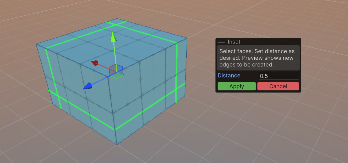
Inset Faces
What it Does: Creates an inset region within each face.
How to Use: Select faces, click “Inset”. Adjust inset amount, confirm.
Preview: Highlighted region shows inset area.
Settings:
- Inset Amount: How far to inset
Subdivide Faces
What it Does: Splits faces into smaller faces.
How to Use: Select faces, click “Subdivide”. Confirm result..
Preview: Wireframe overlay shows new face layout.
Settings: None

Flip Face Normals
What it Does: Reverses the direction of face normals.
How to Use: Select faces, click “Flip Normal”. Confirm.
Preview: Arrows show new direction faces will use.
Settings: None

Conform Face Normals
What it Does: Aligns normals for selected faces.
How to Use: Select faces, click “Conform”. Confirm.
Preview: Face shading updates; preview may show arrows.
Settings: Reverse
- Reverse: Use the minority normals

Triangulate Faces
What it Does: Converts faces to triangles.
How to Use: Select faces, click “Triangulate”. Confirm.
Preview: Wireframe overlay shows triangle layout.
Settings: None

Separate Faces
What it Does: Detaches faces into separate elements.
How to Use: Select faces, click “Separate”. Confirm.
Preview: Highlighted faces show separation.
Settings:
- New Object: If enabled, the selected faces will become a new object
- Duplicate: If enabled, the selected faces will be duplicated, leaving the originals unchanged.

Clear Faces
What it Does: Removes face data (may delete faces).
How to Use: Select faces, click “Clear”. Confirm.
Preview: Faces disappear in preview.
Settings: None

Flip Face Edge
What it Does: Flips triangle edge for better topology.
How to Use: Select triangle faces, click “Flip Tri”. Confirm.
Preview: Wireframe overlay shows edge flip.
Settings: None

UV / Texture Actions
Reset UVs
What it Does: Resets UVs to default.
How to Use: Select faces, click “Reset UVs”.
Preview: None
Settings: None


Project Box
What it Does: Projects UVs using box mapping.
How to Use: Select faces, click “Project Box”.
Preview: None.
Settings: None


Project Planar
What it Does: Projects UVs using planar mapping.
How to Use: Select faces, “Project Planar”.
Preview: None
Settings: None


Flip Horizontal/Vertical
What it Does: Flips UVs horizontally or vertically.
How to Use: Select faces, click “Flip Horizontal” or “Flip Vertical”.
Preview: None.
Settings: None
Fit UVs
What it Does: Fits UVs to face bounds.
How to Use: Select faces, click “Fit UVs”. Confirm.
Preview: UVs fit to faces in preview.
Settings: None

Selection Actions
Grow Selection (Vertex, Edge, Face)
What it Does: Expands selection to adjacent elements.
How to Use: Select elements, click “Grow”. Choose options. Confirm.
Preview: Elements to be selected are highlighted.
Settings:
- Match Color: Will only select elements matching the active element’s color
- Match Material: (Face only) Will only select faces matching active element’s material
- Max Angle: (Face only) Will not expand over edge angles sharper than Max Angle

Shrink Selection (Vertex, Edge, Face)
What it Does: Contracts selection toward active element.
How to Use: Select elements, click “Shrink”. Confirm.
Preview: Elements to be deselected are highlighted.
Settings: None

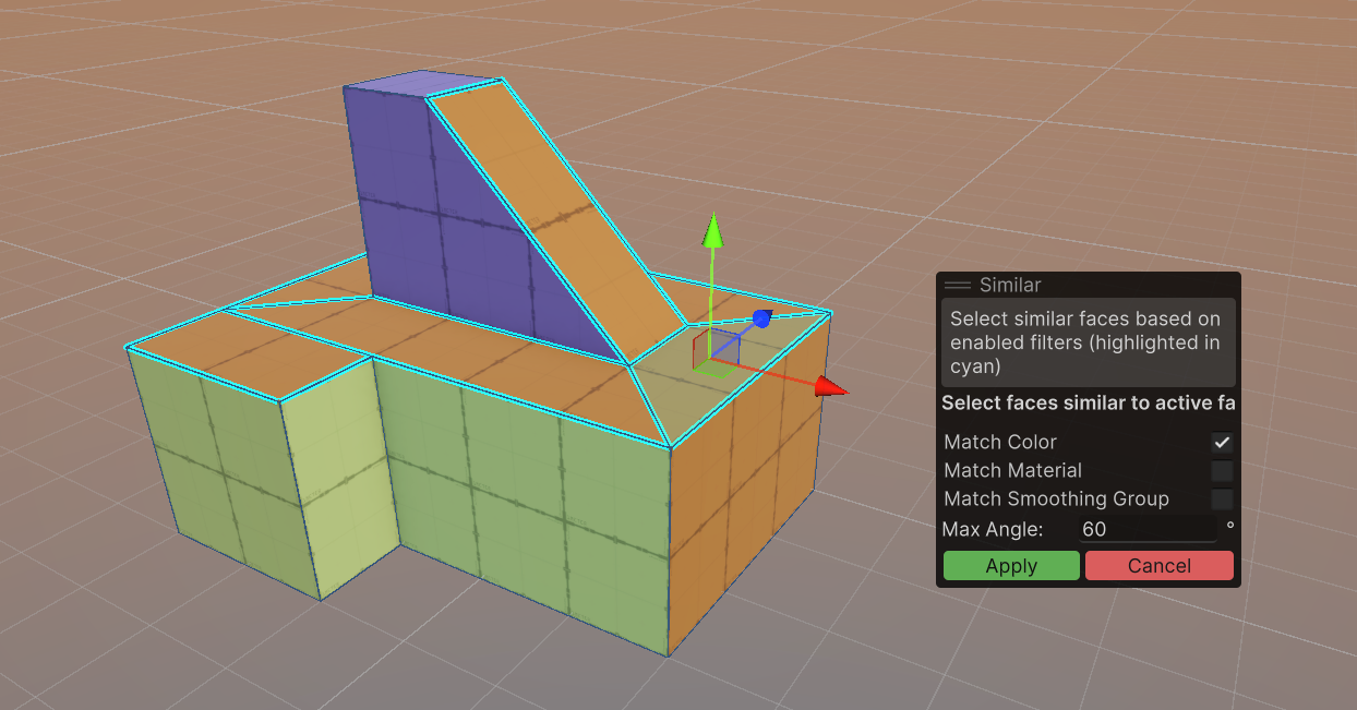
Select Similar Faces (Faces Only)
What it Does: Selects faces with similar properties (does not consider adjacency)
How to Use: Select a face, click “Similar”. Choose options. Confirm.
Preview: Faces to be selected are highlighted.
Settings:
- Match Color: Will only select faces matching the active element’s color
- Match Material: Will only select faces matching active element’s material
- Match Smoothing Group: Will only select faces matching active element’s Smoothing Group
- Max Angle: Will only select faces with normals within this difference
Select Face Path (Faces Only)
What it Does: Selects a “Face Ring/Loop”, depending on selected faces
How to Use: Select two quad faces, click “Face Path”. Confirm.
Preview: None
Settings: None


Select Edge Loop (Edges Only)
What it Does: Selects edge loop.
How to Use: Select an edge, click “Loop”. Confirm.
Preview: None.
Settings: None.


Select Edge Ring (Edges Only)
What it Does: Selects edge ring.
How to Use: Select an edge, click “Ring”. Confirm.
Preview: None.
Settings: None.


Select By Material (Faces Only)
What it Does: Selects faces by material.
How to Use: Select an element, click “Material”. Choose options. Confirm.
Preview: Matching elements are highlighted.
Settings:
- Adjacent Only: If enabled, will only select faces adjacent to the selection (touching it).

Select By Color (Faces Only)
What it Does: Selects elements by color.
How to Use: Select an element, click “Color”. Choose options. Confirm.
Preview: Matching elements are highlighted.
Settings:
- Adjacent Only: If enabled, will only select faces adjacent to the selection (touching it).

Select By Surface Angle (Faces Only)
What it Does: Selects elements by surface angle.
How to Use: Select an element, click “Angle”. Choose options. Confirm.
Preview: Matching elements are highlighted.
Settings:
- Max Angle: Will only select faces with normals within this difference
- Adjacent Only: If enabled, will only select faces adjacent to the selection (touching it).
